What Is a Construction Site Blueprint
Nearly 65% of the project rework resulting from construction quality reports are from misinterpreted drawings and lack of revision updates when the project is on site. A construction blueprint is a series of engineering drawings that provide instructions for the field and specify the dimensions and layout rules, material requirements, etc. for a construction site.
If not interpreted properly, teams will experience alignment issues, inspection problems, and rework cycles which will be cost prohibitive. This framework provides information about how engineering drawings control site work, prevent errors and enhance construction accuracy in real engineering projects.
Types of Construction Blueprints
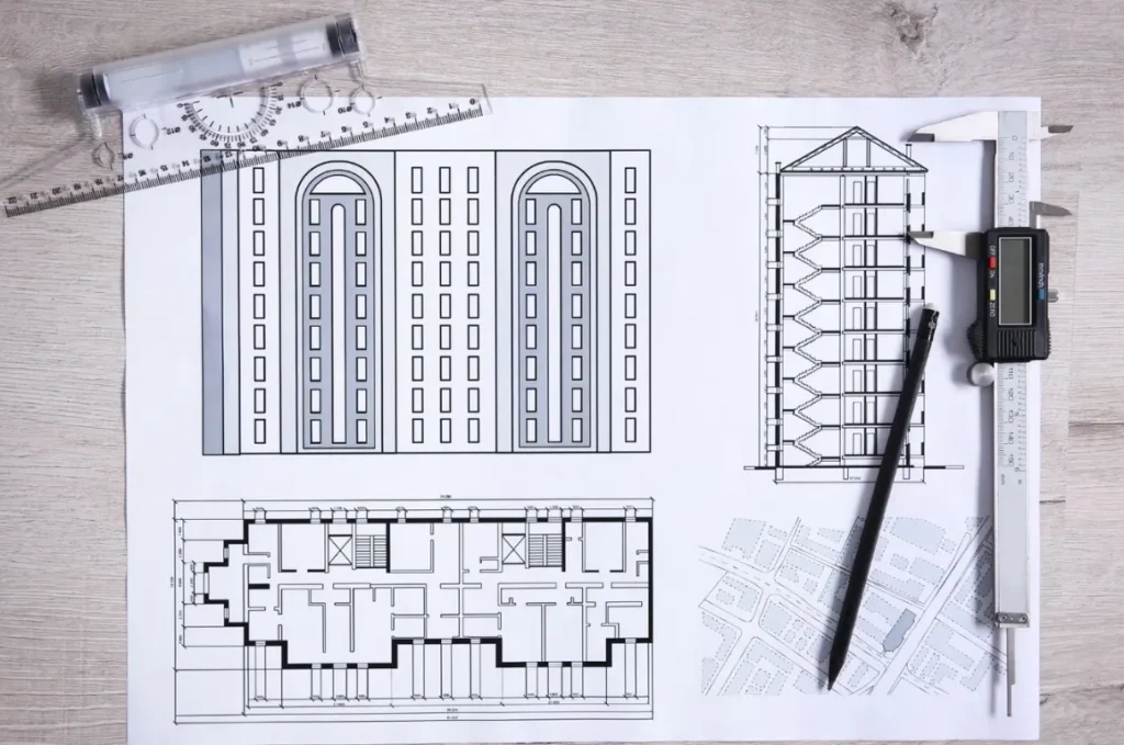
Construction blueprints aren’t a single drawing, but a series of drawings, each of which concentrates on a certain aspect of the building. There is a specific purpose for each type and it aids builders, engineers, and contractors in understanding the project before and during construction.
- Architectural Blueprints: These are drawings that depict the overall structure of the building, including the layout of the rooms, doors, windows, and the overall design of the building.
- Structural Blueprints: These are concerned with the strength of the building, the foundations, beams, columns, and load bearing elements.
- Electrical Blueprints: These are used to show wiring, switch points, lighting layouts and power connections.
- Plumbing Blueprints: These depict water supply lines, drainage and pipe layouts, all throughout the building.
Why Blueprints Are the Backbone of Every Build
Prior to construction, the building of all structures is subject to engineering plans. It is the official field reference for teams.
1. Early Layout Errors
Most of the site errors occur when drawings are not accurately checked prior to application. The slight error in measurement can cause the alignment to be off during inspection, as well as foundation lines to shift.
2. Layout Accuracy Checks
Before any ground marking is done, engineers check the accuracy of the grid points, elevations, and control marks.
Blueprints as a Universal Job-Site Language
Construction drawings serve as a means of communication between design teams and the field crews. They make sure that everyone gets the same directions. All symbols have technical meanings which lead to installation.
1. Construction Drawing Symbols
Symbols are used to define materials, installation techniques and structural components when executing.
2. Revision Control Errors
The old revisions result in incorrect installation and slowdowns in the approvals process, which cause site confusion.
From Paper to Procurement | Material Planning Made Accurate

Construction drawings also help in estimating materials prior to the start of construction. This will help to keep expenses in check and limit waste. Precise measurements help to make better decisions.
1. Drawing Dimensions for Material Calculation
Drawing dimensions aid in the calculation of the materials necessary for concrete, steel and other construction materials.
2. Improving Team Estimation Using Structured Takeoff Methods
In many projects, professionals rely on blueprint takeoff services to accurately measure and quantify materials directly from construction drawings. This process helps determine the required quantities of labor, materials, and equipment, improving estimate accuracy and supporting project planning, budgeting, and procurement decisions before construction begins.
6-Step Field Verification Process for Accurate Blueprint Reading
The field workflow is structured and accurate, and is followed prior to the start of any installation. This process helps to minimize mistakes and help coordinate.
1. Verify title block information
The project name, drawing number, scale and date are confirmed prior to use by teams.
2. Identify drawing discipline
Individual sheets are reviewed for scope of architecture, structure or MEP.
3. Review symbols and legend
Symbols are interpreted to find out installation needs and materials.
4. Confirm revision status
The current approved version is only used on site.
5. Cross-check dimensions with site conditions
The measurements are made against a real ground state to identify mismatches.
6. Check compliance and inspection notes
All codes, tolerances and inspections are checked prior to execution.
This is a systematic way which minimizes misinterpretation and better field coordination.
Costly Blueprint Mistakes Crews Still Make

The majority of the construction delays are due to field work reading repetition errors. These errors have an impact on quality and schedule. Few things are too small to miss on a team, even if it’s an experienced one.
1. Scale Errors Distort Real Layout Positions
If the scale is not used correctly, it will result in inaccurate measurements and misplacements of structures.
2. Ignoring Revision Updates During Active Work
The use of obsolete drawings leads to rework and inspection rejection problems.
3. Poor Coordination Between Field and Design Teams
Lack of communication results in poor implementation on the ground.
Turning Blueprints Into Ground Reality
The structure’s position on site is directly controlled by engineering drawings. They lead the help and implementation steps. They are relied upon by the supervisors for accuracy checks. Survey teams convert the coordinates of the grids into actual GPS coordinates. Supervisors review and approve the next stages of construction by comparing it with the drawings.
The Shift to Digital | Blueprints in Real Time
Today’s building process relies on digital systems for drawing and updates. This helps to achieve better collaboration between teams. It minimizes wrong entry errors due to the out-of-date information.
Information is provided in real time to cover the confusion in the field. All teams are updated versions at once – minimizing risk of mistakes during execution.
1. Collaboration Benefits of Shared Systems
Synchronized data for design, engineering and field is an advantage of shared systems for multi-team coordination.
Blueprint Literacy | The Skill Every Crew Needs
It is critical for field workers to be able to read construction drawings. It is directly related to the success of the project. The quicker and more accurately an interpretation is done, the better.
1. Skills Required for Field Teams
It is necessary to understand symbols, scales and relationships in structure.
2. How Blueprint Understanding Improves Project Delivery
Good reading minimises rework and enhances workflow.
Conclusion
The construction blueprint is an engineered document that is controlled and used for the construction of a project in the real environment. It is a link between design intent and the execution of field work and makes sure that all work is carried out in accordance with the approved requirements.
The ability to see a construction blueprint makes it easier to be accurate, avoid issues with coordination and prevent reworking. While construction systems become increasingly digitalized and in real-time, blueprint literacy is still crucial for ensuring safety and efficiency during construction projects.
FAQs
Q. 1 Which of the following is NOT the purpose of a construction blueprint?
It offers comprehensive information on layout, structure and installation in the construction process.
q. 2 Why Construction Sites get Blueprint Errors?
Typically, errors are made because of an incorrect interpretation or because of a modification that is not the most current, or because of a lack of coordination between teams.
Q. 3 How to deal with changes to drawings for construction teams?
Teams work on updated documents in the project and always use the most up to date approved version on site.
Most Recent
Related Blog Posts
How to Estimate Construction Costs?
Construction cost estimating is one of the most significant phases of any construction job. The financial viability of any residential, commercial, industrial, or infrastructure project with public facilities needs an…How To Read Construction Blueprints
Construction blueprints are technical documents that are used throughout the construction industry in the USA to convey the architect’s design intent to the engineer and contractor. These drawings are the…How to Create a Construction Budget
A construction budget is one of the most important for managing a successful construction project. Any time you’re planning to construct a home, office building, industrial facility, or public building,…